SLA Electro-Mechanical Integration & Custom Base Enclosure CAD
Systematic CAD optimization for a multi-piece SLA photopolymer resin assembly, focusing on internal wire strain relief, power supply bay isolation, and joint alignment under UV post-cure shrinkage.
01. Technical Challenge & Resin Constraints
Integrating electronic components into SLA resin prints introduces specific failure points that differ significantly from thermoplastic FDM prints. Post-cure UV shrinkage can warp mating edges, while the inherent brittleness of cured photopolymer resin makes post-print drilling or machining risky.
- Material Behavior: Cured resin lacks FDM layer flexibility; internal channels must be pre-modeled in CAD to eliminate manual post-machining fracturing risks.
- Cure Shrinkage: Accounted for non-uniform UV post-cure shrinkage across multi-part resin joints to ensure flush seam alignment.
- Strain Relief: Modeled locked wire channels directly into the base structure to prevent solder joint shear on rigid resin walls.
02. Mechanical Execution & Base Modification
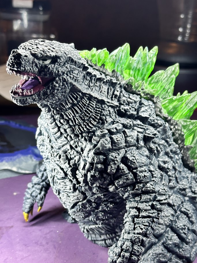
Sub-assembly alignment test ensuring joint seams match before internal routing cutouts are finalized.
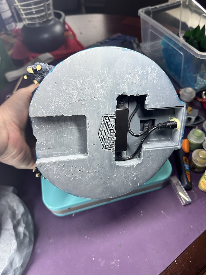
Integrated DC jack socket, wire retainers, and strain relief channel modeled into base structure prior to SLA print.
03. Extended Validation & Iteration Status
The resin prototype assembly is currently undergoing extended runtime testing to validate long-term thermal dissipation and cable harness strain relief under power. While the physical base cavity and routing geometry are verified, final resin shrinkage tolerances are actively being calibrated prior to executing the final production print.
[PASS] Continuous power & thermal dissipation test.
[PASS] Recessed DC Jack socket strain relief verified.
[IN_PROGRESS] Mapping SLA post-cure shrinkage across seam joints.
> SYSTEM_STATUS: Resin cavity validated; locking Rev B CAD tolerances.